3D Delta Printer Calibration
Calibrating Delta Type 3D Printers Running Marlin or Repetier Firmware
The first rule of calibrating a delta printer cannot be overstated: BUILD YOUR PRINTER ACCURATELY. Don't measure twice. Measure three times. It is very important that all three towers are equally spaced and are parallel to each other. Next, the six diagonal rods must be as equally matched in length as possible. The exact length is less important than getting the rods equal in length.
Is your build surface flat? Good! We are going to assume that we have a flat build surface to work with. This should not be an issue if you are using a glass build plate but check the flatness of your build surface anyway, just to be sure. Often, the build surface is mechanically warped by way of being fastened to the printer.
You will need an Arduino environment as well as being familiar with updating the controller's firmware (ie: editing the Repetier or Marlin firmware configuration, compiling it and uploading it to the controller). The printer’s upper end-stops must be working correctly and return as "open" when not engaged and "closed" or "triggered" when pressed. You should also verify that the steps per millimeter (steps/mm) values for your extruder and carriage motors are set correctly in your firmware configuration [steps/mm calculator].
If you have everything above, you are ready to proceed to calibration! Our next steps are:
- Enter some starting values into the firmware.
- Calibrate each of the three towers to the actual build surface.
- Calibrate the firmware to print flat (not dished or cupped) across the build surface.
- Calibrate the firmware to print to correct dimensions.
1. Enter starting values into the firmware.
With your endstop screws about halfway into the carriage (allowing for adjustability in either direction), click the HOME on Pronterface or RepetierHost, and measure the distance from the tip of your extruder to the build surface.
For Repetier, edit:
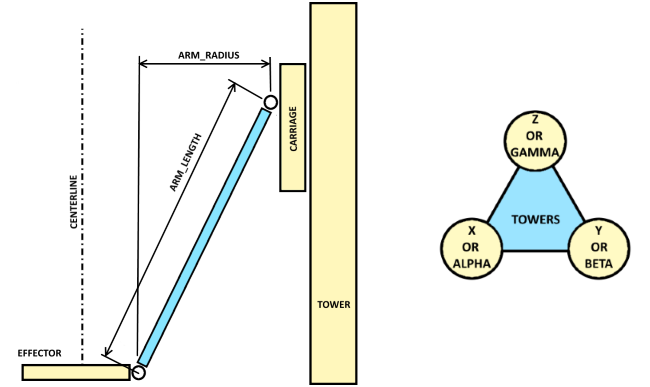
DELTA_DIAGONAL_ROD in Configuration.h END_EFFECTOR_HORIZONTAL_OFFSET in Configuration.h CARRIAGE_HORIZONTAL_OFFSET in Configuration.h PRINTER_RADIUS in Configuration.h Z_MAX_LENGTH in Configuration.h
For Marlin, edit:
DELTA_DIAGONAL_ROD in Marlin.pde/Marlin.ino DELTA_EFFECTOR_OFFSET in Marlin.pde/Marlin.ino DELTA_CARRIAGE_OFFSET in Marlin.pde/Marlin.ino DELTA_SMOOTH_ROD_OFFSET in Marlin.pde/Marlin.ino Z_HOME_POS in Configuration.h
If you built your printer as designed, the default values should be pretty close. Otherwise adjust as appropriate. I like to double check the Z_... value to avoid crashing the extruder tip into the build surface.
2. Calibrate the towers to the actual build surface
An important trick here. Set up four scripts in RepetierHost, or four user defined buttons in Pronterface, to move the carriage to four specific measurement locations on your build surface. Three locations are on a circle centered on the center of your build surface immediately in front of each of the three towers. The fourth is the actual center of your build surface. And each of the four locations is at height Z=0.
Let’s call the three tower locations A, B, and C, and the center D. The script code for each is:
| Button | Script |
|---|---|
| A | g28 g0 f8000 x-77.94 y-45 z0 |
| B | g28 g0 f8000 x77.94 y-45 z0 |
| C | g28 g0 f8000 x0 y90 z0 |
| D | g28 g0 f8000 x0 y0 z0 |
(Decoded, g28 homes the printer carriage, g0 is a move to an absolute location, f8000 controls the speed of the move, and x, y, and z are followed by the corresponding coordinates in 3D Cartesian space. The x and y coordinates are points on a circle 90mm from the build surface center and directly in front of each of the three towers.)
Now run script A in RepetierHost / click button A in Pronterface. The carriage should move up to home, then down to a point in front of tower A. The proper height should be just above the print surface, with clearance space for a single sheet of paper to slide between. Adjust the end-stop screw only for tower A if necessary, then repeat the test by running the script or clicking the button. Repeat until the paper slides between the print surface with only slight drag.
With tower A adjusted, move on to tower B, and then to tower C. When tower C is adjusted, you should be able to go back and successfully repeat the test on tower A without having to readjust.
3. Calibrate the firmware to print flat
At this point, it is likely that if the firmware instructs the printer to move the carriage across the build surface, the nozzle tip will not stay true to the build surface. Even though the extruder will be at the calibrated correct Z height at each of the three tower locations, it will either be above or below the build surface at the center of the build area. This is also corrected by adjusting the firmware.
Run script D / click button D. The carriage should move up to home, then straight down to the center of the build surface. You will see one of three things. The extruder nozzle will be above the build surface, at just the right height (using the paper test), or will hit the build surface.
The value in the firmware constant DELTA_RADIUS (both Repetier and Marlin) controls the “flatness” of the movement of the carriage at a given Z height. If DELTA_RADIUS is too large, the extruder nozzle will track below the desired Z height inside the calibrated points A, B, and C. If DELTA_RADIUS is too small, the extruder will track above the desired Z height inside the calibrated points A, B, and C.
However, in both Repetier and Marlin (as the code is written), you don’t adjust DELTA_RADIUS directly. DELTA_RADIUS is calculated from the initial values entered earlier:
For Repetier in Configuration.h
DELTA_RADIUS is PRINTER_RADIUS - END_EFFECTOR_HORIZONTAL_OFFSET -CARRIAGE_HORIZONTAL_OFFSETFor Marlin in Marlin.ino.Marlin.pde
DELTA_RADIUS is DELTA_SMOOTH_ROD_OFFSET - DELTA_EFFECTOR_OFFSET -DELTA_CARRIAGE_OFFSET
To correct the problem, the best course is to change one of the variables set earlier to force the value of DELTA_RADIUS to increase(to lower the extruder nozzle) or to decrease (to raise the nozzle).
To lower the extruder nozzle increase DELTA_RADIUS by increasing DELTA_SMOOTH_ROD_OFFSET(Marlin) or PRINTER_RADIUS(Repetier).
To raise the extruder nozzle, decrease DELTA_RADIUS by decreasing DELTA_SMOOTH_ROD_OFFSET(Marlin) or PRINTER_RADIUS(Repetier).
For your first cycle, if you are above the build surface, increase DELTA_RADIUS by (about) the same amount. If the extruder nozzle hits the build surface, decrease DELTA_RADIUS.
Next, repeat the ABC tower calibration process. Changing the DELTA_RADIUS changes the tower calibrations, so you must cycle through the process of adjusting the ABC buttons/scripts again. And when the ABC towers are set, test the center D button/script.
You may have to repeat this a few times with smaller changes to DELTA_RADIUS, but eventually, the drag on a piece of paper should be the same at all four locations. Now the printer knows how to print flat at a given Z height.
4. Calibrate the firmware to print to correct dimensions
At this point the printer probably prints, but the results are dimensionally wrong. Printing something 100mm long results in a printed object that is not exactly 100 mm long. This also, can be corrected in firmware. Adjustments to DELTA_DIAGONAL_ROD in the firmware control the size of the printed object.
Create a simple calibration object in OpenSCAD, slice it, and print it. By measuring the actual size of the object as printed and comparing it to the size in the design, the accuracy of the printer can be assessed and adjusted.
Here is my sample OpenSCAD object:
cube([100,2,2]));
If the length of the object is wrong, adjust DELTA_DIAGONAL_ROD:
    new DELTA_DIAGONAL_ROD =
    100 / measured_length * original DELTA_DIAGONAL_ROD
then re-upload the firmware, and print and measure again. When the printed object measures 100 mm, the printer is printing accurately to size and is fully calibrated.